At QuestDB, we have a JIT compiler for the WHERE clause of SQL queries. We implement it with hand-coded SIMD instructions — such as the one from the title. When I started working here, I have to admit — these instructions scared me! But, once I sat down to study them, it turned out to be much less scary, in fact, not scary at all. It just took some getting used to.
This article provides a gentle intro to what I found out, and shares how I got to write some SIMD code of my own. Much of the obscurity comes from unfamiliar jargon. Let me deal with a few items of that first, to ease you into the topic.
What exactly is a SIMD instruction?
SIMD stands for "Single Instruction, Multiple Data". Before studying it, I had
this mental model that such an instruction would run some equivalent of a loop
to do work on a block of memory. In fact, even the original 8086 instruction set
has a few instructions like that, for example repne scasb scans a whole string
for a matching byte!
The actual selling point of a SIMD instruction is not "multiple data" itself, but "multiple data in parallel". Another non-obvious thing I found out was that a SIMD instruction operates on a CPU register, just like a "regular" instruction, and not on a block of memory of arbitrary size.
A traditional register represents a single value, for example a 64-bit integer. If you are processing a collection of items, you have to do it one by one:
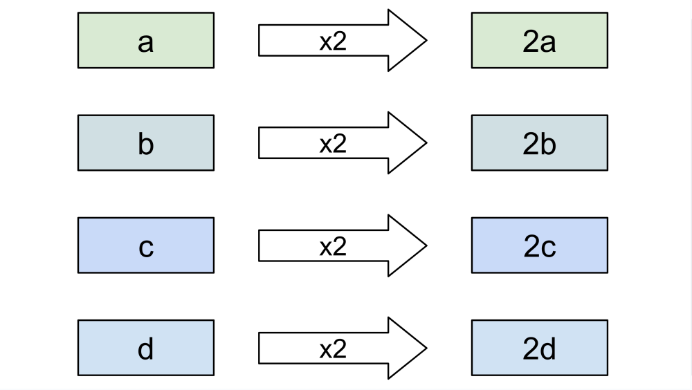
SIMD instructions use their own special registers, which represent vectors of values. Just like a regular register, a SIMD register has a fixed size, for example 256 bits. However, a given SIMD instruction can see the contents of that register in many different ways: as four 64-bit integers, or eight 32-bit integers, or even thirty-two 8-bit integers. Some other instructions can use the same register as a vector of floating-point values instead of integers.
A single SIMD instruction therefore has the effect of processing several items at once:
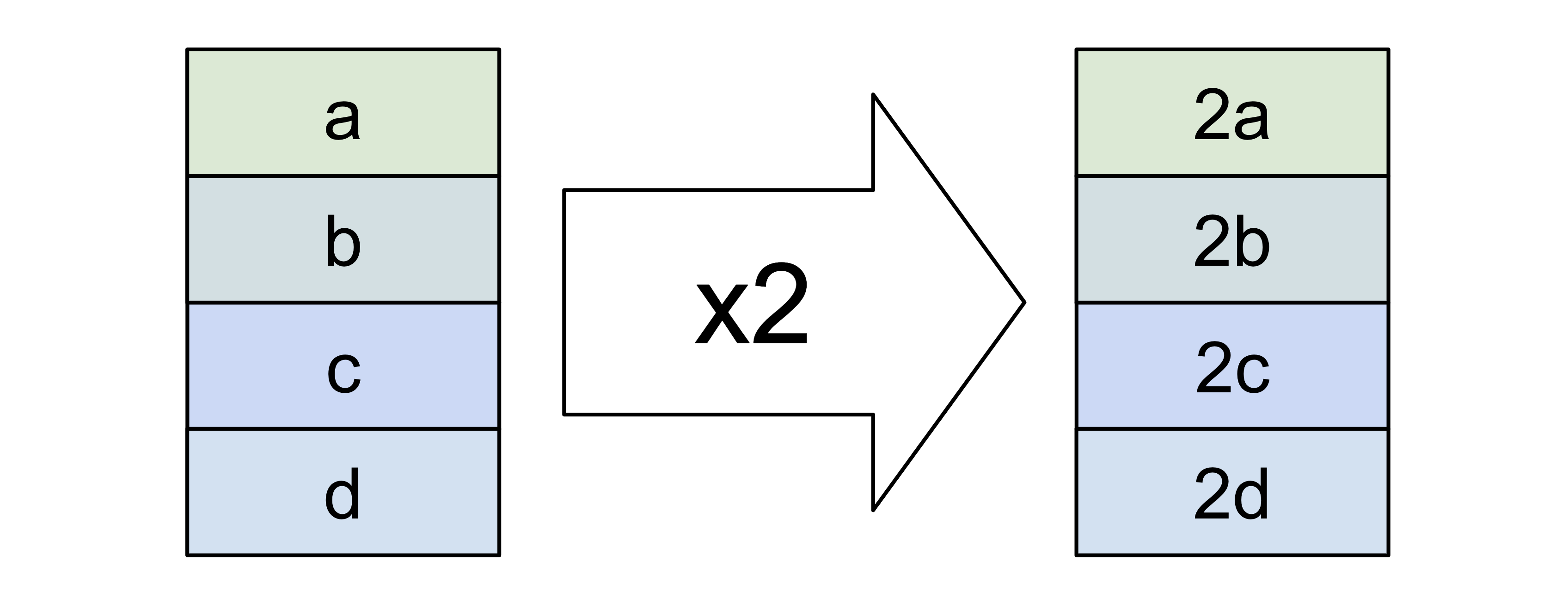
Since the data doesn't just appear in registers on its own, SIMD instructions also deal with copying vectors between memory and registers.
"Vector" vs. "Scalar"
To contrast with the vector registers, we sometimes refer to the traditional registers as "scalar". This naming comes from linear algebra, where we deal with vectors and scalars, a scalar being simply a number.
Evolution of SIMD registers
As the years have gone by, SIMD register sizes have grown. To name a few milestones:
- Streaming SIMD Extensions (SSE) introduced 128-bit registers, called XMM
- Advanced Vector Extensions 2 (AVX2) doubled that to 256-bit, and called the new registers YMM
- AVX-512 went up to 512-bit registers, and called them ZMM. That's 64 bytes in a register — a full CPU cache line!
The quantity of these registers has also grown: from eight XMM registers available in a Pentium III (1999) to as many as 32 ZMM registers in the latest AVX-512 equipped processors.
Those scary mnemonics
vpmovzxbd, vmovmskpd, vpermps… have you seen these sometimes and felt your
brain immediately shut down? I sure have. The mnemonics of the original x86
instruction set are simple, like mov and add, because their descriptions are
also simple.
With these vector instructions, whole complex sentences get compressed into less than a dozen letters.
To make them less scary, you have to learn how to quickly parse them. They
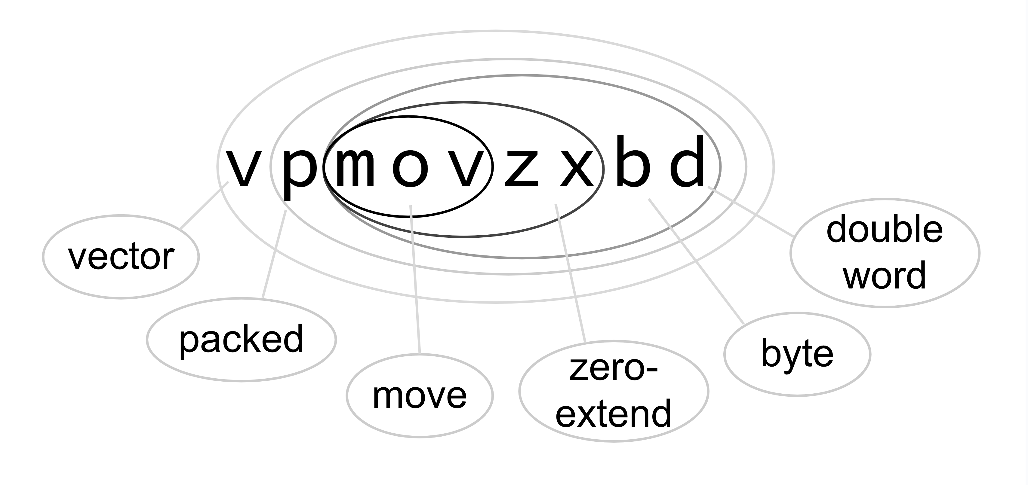
unpack like a matryoshka doll. For example, in vpmovzxbd:
- the core is
mov: "move" (actually copy) values zxmeans "with zero extension" (as opposed to sign extension)movzxis a pre-existing x86 mnemonicpstands for "packed", and means the values are placed right next to each other, without any paddingvmeans "vector" and signals an AVX instructionbis for "byte", an 8-bit integerdis for "double word", a 32-bit integer
So, this means "an AVX instruction that moves (copies) in parallel a vector of 8-bit values packed into the lowest part of the source register to a vector of packed 32-bit values, zero-extending them."
The term "double word" for what's mostly known as an "int" comes from way back
in the 80's, when the 8086 CPU understood only two things: an 8-bit byte and a
16-bit word. As the x86 instruction set evolved, no names were ever changed,
only new ones came along, consistent with the existing ones. You may now wonder
"So what's a 64-bit value called? A quadruple word??" Believe it or not, that
is exactly what it's called! We just shorten it to "quad word", and the
mnemonics use even shorter names: dword and qword.
Vector registers are Little-Endian
When I wrote SIMD code for the first time, I hit this gotcha: I imagined a vector register (called YMM) as a copy of a 256-bit block of memory. I didn't even realize that this meant I was imagining a big-endian layout in the register, which Intel CPUs clearly are not! I even managed to write some correct code with this wrong picture in my head, because it happened to be symmetrical and the ordering didn't matter. Then I moved on to another problem, and ended up banging my head for hours trying to figure out why it was misbehaving.
If you aren't familiar with these terms, just keep reading — we'll explain them visually in the examples below.
What's the typical performance of a SIMD instruction?
I spent some time browsing the Intel Intrinsics Guide (a great, interactive webpage, BTW), and as a rule of thumb you can count on a typical SIMD instruction taking 3 CPU cycles to execute. Thanks to pipelining and/or parallel execution units, the throughput of a sequence of SIMD instructions can be expected to clock in at around one instruction per cycle — pretty great!
So… how do these instructions help you with SQL?
The key to using SIMD effectively is placing data of the same type close together. In other words, you have to store your database records column by column, and not row by row, as it's done in the traditional OLTP databases. That's what we do in QuestDB. Once you have it arranged like that, you can perform the same operation on many values in a single instruction, in parallel.
We do it with AsmJit
If you want to JIT-compile a WHERE clause, you have to create a block of memory, fill it with bytes that the CPU will understand as instructions, and then point the CPU's Instruction Pointer (IP) register at it. If you do this from scratch — write all the code to output just the right bytes — you'll have to study every last paragraph of the Intel Software Developer's Manual, a mere 2522 pages!
We decided that would be way too much fun for us, so instead we use this cool library called AsmJit. It's a very lightweight, yet very convenient and powerful API that lets you emit individual Intel instructions. When you use it, your C++ code starts looking like assembly, here's a sample:
Gp next_index_qword = c.newInt64("next_index_qword");
c.mov(next_index_qword, qword_ptr(varsize_aux_address, input_index, offset_shift, 32));
Ymm next_index_data = c.newYmm();
c.vmovdqa(next_index_data, index_data);
c.pinsrq(next_index_data.xmm(), next_index_qword, 0);
c.vpermq(next_index_data, next_index_data, 0b00111001);
What's even cooler about AsmJit is that it handles a few of the very tedious concerns when writing assembly. You can create any number of virtual registers that correspond to your higher-level thinking in terms of variables, and AsmJit figures out what CPU register to use for each of them.
If you use too many variables at once, it will transparently "spill it over" to a location on the stack. It also deals with reserving memory space for constant values that you'll need in your code. It can even do dynamic memory allocation, but we don't use that feature.
Learn by example
Let's now dig into some real-life examples to give you an idea how you go from a problem statement to a solution with SIMD instructions.
"IS NOT NULL" for VARCHAR
Our soon-to-be-released VARCHAR column is stored in two data vectors:
- The data itself, UTF-8 string values placed back-to-back
- The auxiliary vector with fixed-size structures describing each value
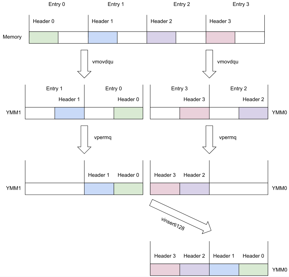
To perform a null check, we don't need the data vector at all; we can just inspect the bits in the auxiliary struct. It is 16 bytes long, and the first 8 bytes will contain a specific pattern that tells us the value is NULL (actually it's just a single-bit flag, but it's easier to compare the full quadword (8-byte, or 64-bit, value) with the expected value). So what we need to do, is collect four of those 8-byte header parts into a single YMM register, and compare them with a constant that indicates a NULL.
This is the relevant snippet:
; load the NULL constant to all 4 qwords in ymm2:
vpbroadcastq ymm2, qword ptr [L4+32]

; load first 32 bytes to ymm1 (rbx is base pointer, rcx is offset):
vmovdqu ymm1, ymmword ptr [rbx+rcx]

; load next 32 bytes to ymm0:
vmovdqu ymm0, ymmword ptr [rbx+rcx+32]

; move headers 0,1 to the lower part of ymm1:
vpermq ymm1, ymm1, 8 {0|0|2|0}

; move headers 2,3 to the upper part of ymm0:
vpermq ymm0, ymm0, 128 {2|0|0|0}

; copy headers 0,1 to lower part of ymm0:
vinserti128 ymm0, ymm0, xmm1, 0

; compare all 4 headers in ymm0 with constant in ymm2:
vpcmpeqq ymm1, ymm0, ymm2
And here's a visual explanation of what's going on:
Little-endian order revisited
First take note of the reverse-order arrangement of the data in the ymm
registers compared to memory: this is the little-endian order we mentioned
earlier.
Counterintuitive at first, this ordering is an artifact of the way we visualize the bits inside a register. We show them in the right-to-left direction, because that's how we write our numbers: the digit numbered zero is the rightmost one.
Little-endian ordering of the data in the register is actually the natural one: a byte from a lower address in memory ends up in a lower-numbered byte in the register.
The Permute instruction
How does vpermq ymm1, ymm1, 8 {0|0|2|0} achieve the arrangement we want? It
says "take the four quadwords (64-bit values) from ymm1, and store them back
to ymm1, using this template to see which part goes where: {0|0|2|0}."
The entire template is encoded in eight bits, two bits per slot, and together
they spell out the number 8. So, it will store the lowest quadword (from
position 0) to all the positions except position 1, where it will store the
quadword from position 2.
If you look at the left part of our picture, you can see that Header 0 is at
position 0 in ymm1, and Header 1 is at position 2. So, after the
permutation, we end up with Header 1 at position 1, and Header 0 at position
0.
We also place Header 0 to the upper two positions, but we don't care about that data, it will be discarded.
Once we have the data all nicely packed into ymm0, we use vpcmpeqq to
compare the headers with the constant value that indicates a NULL.
"IS NOT NULL" for BINARY
Our BINARY column is also stored in two vectors, but in a different arrangement than VARCHAR:
- The data vector contains the values, each prefixed by a 64-bit header telling the size, or -1 for NULL
- The auxiliary vector contains the offset of each entry in the data vector
When checking which values are NULL, we can simply check the headers in the data vector for -1. But, that's expensive: you must first access the auxiliary vector to fetch the offset of the value, then fetch the header at that offset in the data vector.
Whenever you load a value from memory whose location you just calculated, you're performing a data-dependent load. This has implications for performance, because the CPU won't know the address from which to load until the last moment, so it won't be able to tell the memory subsystem to start working on that fetch in advance.
What we do instead is based on this simple observation: if the successive values in the auxiliary vector, i.e., the offsets of successive entries in the data vector, differ by just the size of the header (8), it means that this value is either NULL or empty. But if the difference is greater than 8, then the value is definitely not NULL.
So we first do the optimistic calculation of offset differences, hoping they all come out greater than 8, and if they do, we're done — all the tested values are non-NULL.
If any turns out to be 8, we enter the slow path, where we load the actual header values, which we'll later compare with -1 (the NULL marker value).
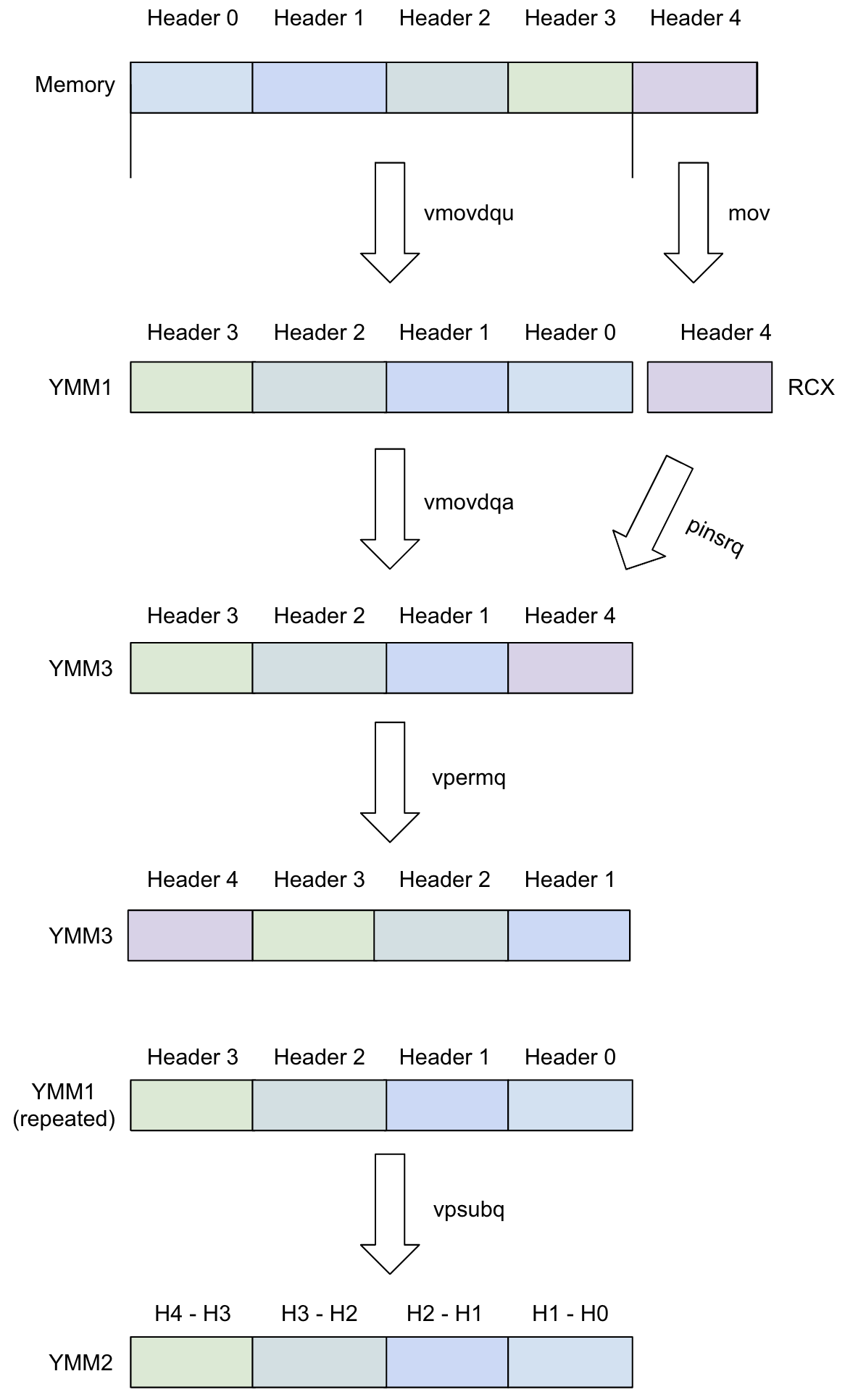
The fast-path part is the more interesting one, let me show you just that bit:
; load Headers 3,2,1,0 into ymm1 (r10 is index of Header 0):
vmovdqu ymm1, ymmword ptr [rcx+r10*8]

; load Header 4 into rcx:
mov rcx, qword ptr [rcx+r10*8+32]

; copy ymm1 to ymm3:
vmovdqa ymm3, ymm1

; replace the Header 0 in ymm3 with Header 4:
pinsrq xmm3, rcx, 0

; bring the headers in ymm3 into proper order (4,3,2,1):
vpermq ymm3, ymm3, 57 {0|3|2|1}

; do header(n + 1) - header(n), put result in ymm2:
vpsubq ymm2, ymm3, ymm1

; load constant 8 from memory to all quadwords in ymm0:
vmovdqa ymm0, ymmword ptr [L4+96]

; subtract 8 from all numbers in ymm2:
vpsubq ymm2, ymm2, ymm0

; zero out ymm0:
vpxor ymm0, ymm0, ymm0

; compare ymm2 with zero, result in ymm0:
vpcmpeqq ymm0, ymm2, ymm0

; copy all comparison results to ecx:
vpmovmskb ecx, ymm0

; see if any bit is one (means that some quadwords in ymm2 are zero):
test ecx, ecx

; if not, all the binary values are non-null, we're done:
jz L5

; enter the slow path, not shown here

L5:
Visualized:
The dreaded "SSE/AVX transition"
There's another pitfall awaiting an unsuspecting SIMD instruction handcoder: you should never mix legacy SSE instructions with AVX instructions!
This is because SSE's XMM register is integrated as the lower half of AVX's YMM, and the legacy SSE execution hardware doesn't know anything about that upper half. So the CPU, whenever it sees an SSE instruction while already processing AVX, is forced to back up the entire YMM upper-half state, so it can bring it back in if it encounters an AVX instruction later on. This is said to cost dozens of CPU cycles.
The difference between SSE and AVX instructions is easy to spot by the prefix
v that all the AVX instructions use.
Now, if you go back to our code samples, you'll actually see a potentially
offending instruction pinsrq. I discovered that just while writing this post.
Naturally, this got us QuestDB engineers worried and we did a quick test. We
used the Intel tool sde to detect SSE/AVX transitions, and also ran some
benchmarks before/after replacing the offending instruction with the AVX
equivalent.
For some reason, no SSE/AVX transition showed up in sde's report, and
there was no effect on performance. We're still not sure what's going on — but
if you ever end up writing Intel SIMD, definitely have this on your mind!
Conclusion
While interesting, I realize that the skill of handcoding SIMD isn't particularly in demand on the job market. But it does resonate with that geeky string in us! It's a fun challenge and maybe a cool pub trick to pull on your programmer friends.
Hopefully this post shines some cheerful light on this obscure, yet intriguing topic. I learned several new things about SIMD while writing it!